A gas burner works by mixing gas fuel with the correct proportion of air for combustion. The simplest and most commonly used gas burners for natural gas or LPG are atmospheric or Venturi burners. They require no blower or moving parts. This article outlines their principles of operation, providing a basis for fault-finding and diagnostics.
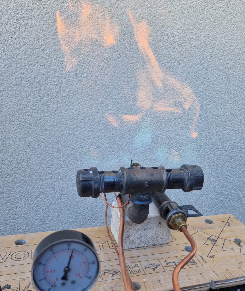
Atmospheric burners allow gas to flow through a small orifice into the burner, where the high-speed gas jet entrains air. They are very reliable, whether the gas supply is a low-pressure fixed installation or from higher-pressure portable cylinders. They are relatively cheap to buy and easy to make using standard plumbing components.
Alternative designs use a powered blower to mix pressurised air with the gas, enabling automated kiln atmosphere control. Power burners can deliver high heat output but add complexity and cost, so they are seldom used in craft pottery kilns and are not covered here.
Burners are usually mounted separately from the kiln, with each flame directed through an opening in the base or side of the kiln. Heat input is easily regulated by adjusting the gas flow, so provided the total capacity of burners is sufficient for the kiln, the exact rating of each burner is not critical.
Key parts and principle of operation
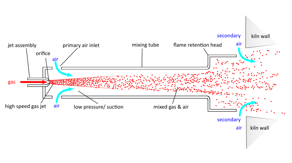
- Gas enters the burner through a small orifice in the jet.
- The high-speed gas jet reduces the nearby air pressure, drawing in surrounding air through the primary air inlets.
- Turbulent flow mixes air and gas ready for combustion.
- The flame retention head slows down the gas air mixture to provide a stable flame.
- Additional air, known as secondary air, is introduced through or around the burner head to allow complete combustion.
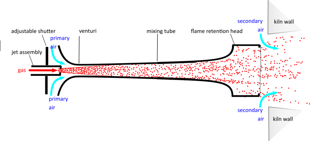
The physical design, shape and proportions of burners varies, but all have the essential parts illustrated in Fig 1. Most commercial burners are designed to be interchangeable between gases with small differences to allow for the correct rates of gas and air. Many are based on castings with a converging/ diverging shape known as a venturi throat that increases the velocity of the gas/air mixture. These provide better control at low pressures and can use a shorter mixing tube than parallel tube burners. See Fig.2.
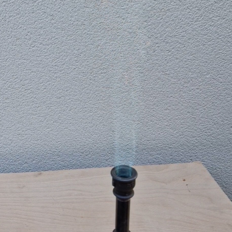
The burner must mix correct proportions of gas and air and release the mixture at the burner head where it burns. Note that only about 60% of the total air is drawn in as primary air; the remainder enters the kiln as secondary air where the flame inters the kiln.
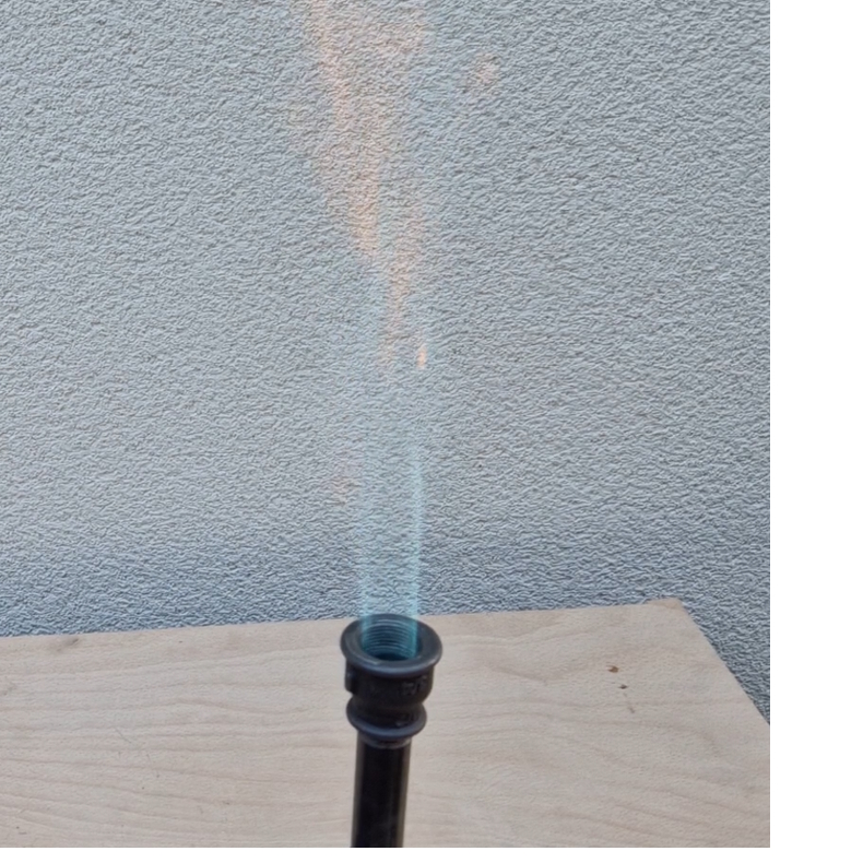
A key point is the speed of the gas air flow at various stages through the burner. It must be fast enough to draw in air and prevent the flame from burning back in the mixing tube but must leave the burner head slowly enough to prevent the flame from lifting off.
Jet assembly and orifice
The size of orifice in the jet controls the volume of gas entering the burner at any particular pressure and determines the nominal heat output of the burner.
- The high-speed gas jet drags along the air around it, reducing the nearby air pressure and drawing in surrounding air through the primary air inlets.
- The heat output available from the burner is directly proportional to the area (not the diameter) of the orifice.
- Standard interchangeable gas jets are widely available as they are used to convert gas appliances between natural gas and propane.
Primary air inlet
- The free area of the air inlet controls how much air is drawn in by the jet of gas.
- To adjust for different gases and orifice sizes, the size of the air inlet is usually adjustable, but burners designed for a specific gas and pressure range may have no adjustment.
- Venturi burners use a threaded shutter, and parallel tube burners use a sliding collar.
Venturi throat
The venturi is a constriction in the throat of the mixing tube.
- It compresses the gas, increasing its velocity and helping to entrain more air.
- It provides a greater range of turn-down, allowing more control at low pressure.
Mixing tube
The mixing tube must be large enough to create turbulent flow and allow the air and gas to mix thoroughly.
- The mixing tube on a venturi style burner can be shorter than a parallel tube
Flame retention head
The retention head slows down the flow of gases exiting from the burner and is matched to the capacity of the burner.
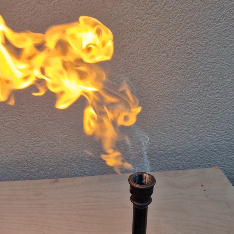
- It must be larger than the mixing tube so that it slows the gases down to prevent the flame lifting off.
- If it is too big, then the flame will travel too slowly and will burn back into the tube and ignite at the primary air inlet.
- Burner heads can have multiple outlets to shape the flame pattern and may also include secondary air inlets to provide more stability.
Entry to kiln
Finally, the burner flame is directed through a hole in the base or side of the kiln, where it sweeps secondary air into the kiln. The amount of secondary air is controlled by:
- The size and shape of the entry hole
- The distance of the burner from the entry hole
- The pull of the chimney
Our separate burner design article will be published shortly. This includes detailed dimensions for DIY burners, natural gas, propane and other gas burners. There is also a table giving common orifice sizes with nominal output ratings for various gases at pressures up to 2 bar (29 psi).